
What is pultrusion in composite manufacturing
Pultrusion is a continuous composite manufacturing process in which fiber rovings are pulled through a resin bath and a heated die to yield a solid profile of constant cross-section. Its name is a portmanteau of pull and extrusion.
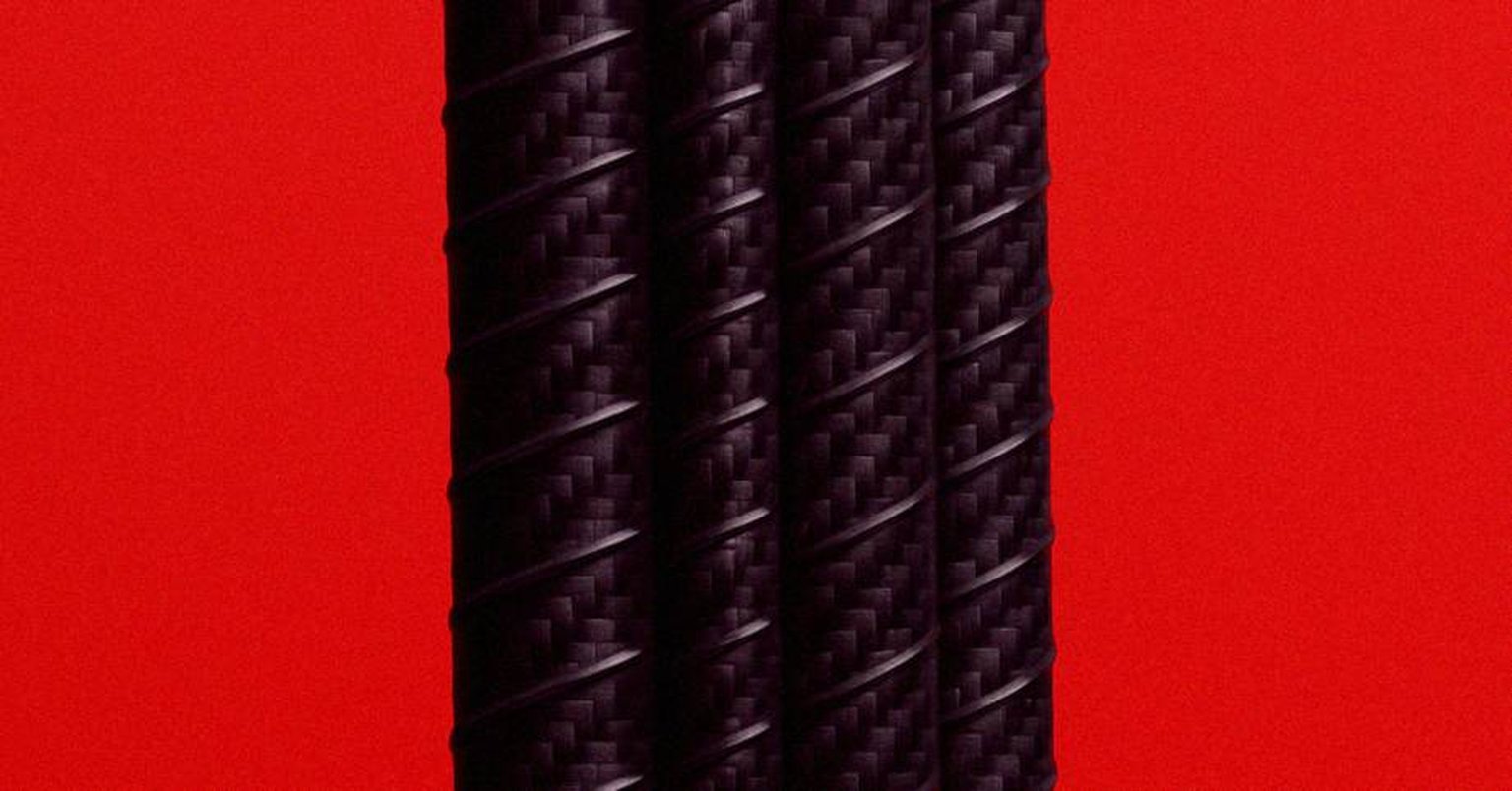
Pultrusion is a continuous composite manufacturing process, its name a portmanteau of pull and extrusion. Fiber rovings and mats are pulled through a resin bath and then a heated die, where the resin cures to yield a solid profile of constant cross-section. Pull-tension load cells and die temperature controllers monitor the run.
The process is well suited to high-volume, uniform profiles with high axial properties: beams, rod, rebar, channel, utility poles, and bridge profiles. The geometric trade-off is built into the die: variable cross-sections and complex curved shapes are out of reach.
How to recognize a pultruded part#
Three features identify a pultruded profile.
The cross-section is constant along the entire length of the part. A pultruded I-beam looks identical end-to-end; a pultruded carbon rod has the same diameter at any point along its length. Variation along the length is geometrically impossible in single-pass pultrusion.
The fibers run parallel to the pull direction with very tight alignment. Cross-sections cut from a pultruded part show fiber bundles oriented along the axis with little of the waviness, crimp, or off-axis content seen in woven, wound, or laid-up parts. Off-axis reinforcement, when present, comes from continuous-filament mat or stitched fabric layers integrated into the preform before the resin bath.
The fiber volume fraction is high. Pultruded structural sections commonly run Vf above 65 percent, with carbon spar-cap pultrusions reaching the upper end of that range. The high Vf is one of the reasons pultrusion replaced infused and prepreg layups on utility-scale wind blade spar caps.
Surface finish is uniform and shaped by the die geometry rather than by a tool side and a bag side. Both faces of a pultruded section are die-formed, similar to what closed-mold processes like RTM deliver and unlike the asymmetric finish typical of vacuum-bag layups.
Where pultrusion is used#
Four application categories cover most pultruded volume.
Civil and structural profiles. Glass-fiber pultruded beams, channels, angles, and gratings carry load in chemical plants, water-treatment facilities, and offshore platforms where corrosion resistance, electrical insulation, and weight matter more than absolute stiffness. Carbon pultruded sections appear in long-span footbridges and seismic-retrofit cable systems.
Reinforcement bar and dowel. BFRP (basalt fiber reinforced polymer) rebar is pultruded, with continuous basalt filaments embedded in epoxy or vinyl ester to produce a non-corrosive alternative to steel rebar. The product does not rust under chloride exposure and is used in coastal bridge decks, salt-exposed slabs, and electrically insulating reinforcement applications. GFRP rebar follows the same process route.
Wind-turbine spar caps. Pultruded carbon spar caps replaced infused glass and carbon-epoxy prepregs on utility-scale wind blades, especially in the 60-meter-plus class. The motivation was consistency: Vf greater than 65 percent, near-perfect fiber alignment, and elimination of the micro-waviness that affected infused spar caps. Vestas, Siemens Gamesa, and several Chinese manufacturers operate pultrusion lines for spar caps, with cap stacks bonded into the shell during blade assembly.
Yacht and tower rigging, and standing rod. ECsix carbon-rod rigging consists of bundles of pultruded carbon rods, typically 1 to 2 mm in diameter, packed into a tight circular cross-section. The multistrand architecture absorbs bending and impact energy without initiating crack propagation through the section, and the high pultruded Vf gives the rigging its very high modulus-to-weight ratio. Standing carbon rod for masts, antennas, and instrument booms shares the process.
Confusion points#
Pultrusion versus extrusion. Extrusion pushes molten material through a shaped die under pressure. Pultrusion pulls reinforced material through a shaped die under tension. The reversal matters: pulling keeps the continuous fibers taut and aligned, while pushing would buckle and bunch them. Aluminum extrusions and pultruded fiberglass profiles look similar on a shelf and share the constant-cross-section format, but the process physics are opposites.
Pultrusion versus filament winding. Both are automated continuous processes. Pultrusion yields straight constant-section profiles with fibers parallel to the pull axis. Filament winding yields hollow axisymmetric parts with fibers at the wound helical or hoop angle. Pultruded carbon rod runs straight; a filament-wound pressure vessel is shaped over a mandrel.
Pultrusion versus pultruded layup in a wind spar cap. A spar cap is built up from many pultruded carbon plates stacked and bonded into the blade shell during assembly. The plates are pultruded; the spar cap as a structural element is an assembly. The Vf reported for the spar cap is the Vf of the constituent pultrusions.
Curved pultrusion. Pull-winding and curved-pultrusion processes extend the geometric envelope to mild constant-curvature profiles by adding a curved die or by post-forming the section in a secondary die before final cure. The output is still constant cross-section along the (now curved) pull path.
Pultrusion is not a layup method. Pultrusion does not lay up plies in the layup-by-orientation sense. Fiber orientation in a pultruded section is set by the rovings and mat layers integrated into the preform before the resin bath. Designers tune the off-axis content through preform composition, not through stacking sequence.
Related terms#
- Fiber volume fraction (Vf): the consolidation metric that pultrusion drives higher than most alternative processes.
- Filament winding: the closest continuous-process relative, restricted to hollow axisymmetric parts.
- Resin transfer molding (RTM): the closed-mold contrast for complex 3-D shapes at moderate volumes.
- Prepreg: the alternative reinforcement format for parts where shape complexity rules out pultrusion.